Power Converter Construction
Parts required for voltage converter cable

- (1) buck converter
- (2) male jst pins
- (1) jst 2 pin male connector
- (1) 7cm red wire
- (1) 12cm white wire
- (1) 2cm 3/16" heat shrink
- (1) 5cm 3/8" heat shrink
- (1) female barrel jack
Steps to make a 12v-5v converter cable

The default configuration of the buck converter is variable output voltage. The potentiometer needs to be removed from the circuit to set a constant voltage.

The easiest way to do this is to completely remove the potentiometer from the board.

The solder pads must be bridged for the desired constant voltage.

Bridge the 5v pads to set output voltage to 5v.


Strip 2-3cm off the end of the red wire and insert it from the under side into the IN+ hole and back down through the EN hole


Solder the top side and the bottom side. After soldering, trim the excess wire.


Strip and feed the white wire through the GND hole and solder in place. Then strip and feed the red wire through the VO+ hole and solder in place. Trim both wires.
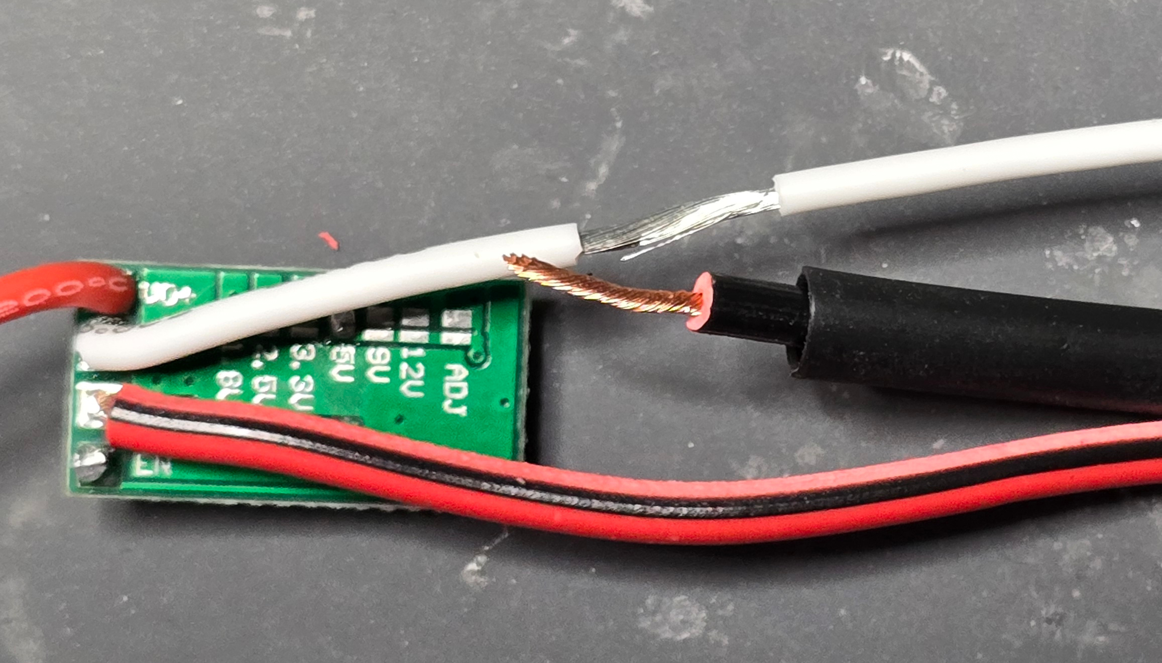
Strip about 1cm of the white wire just after the end of the PCB. Strip about 1cm of the black wire from the barrel jack and feed the 3/16" heat shrink on.
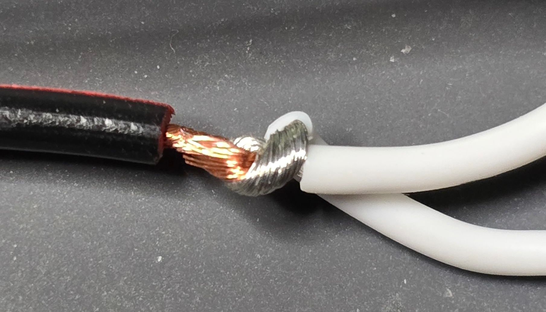
Create a hook in the black wire, hook it over the stripped section of the white wire and wrap them around each other.
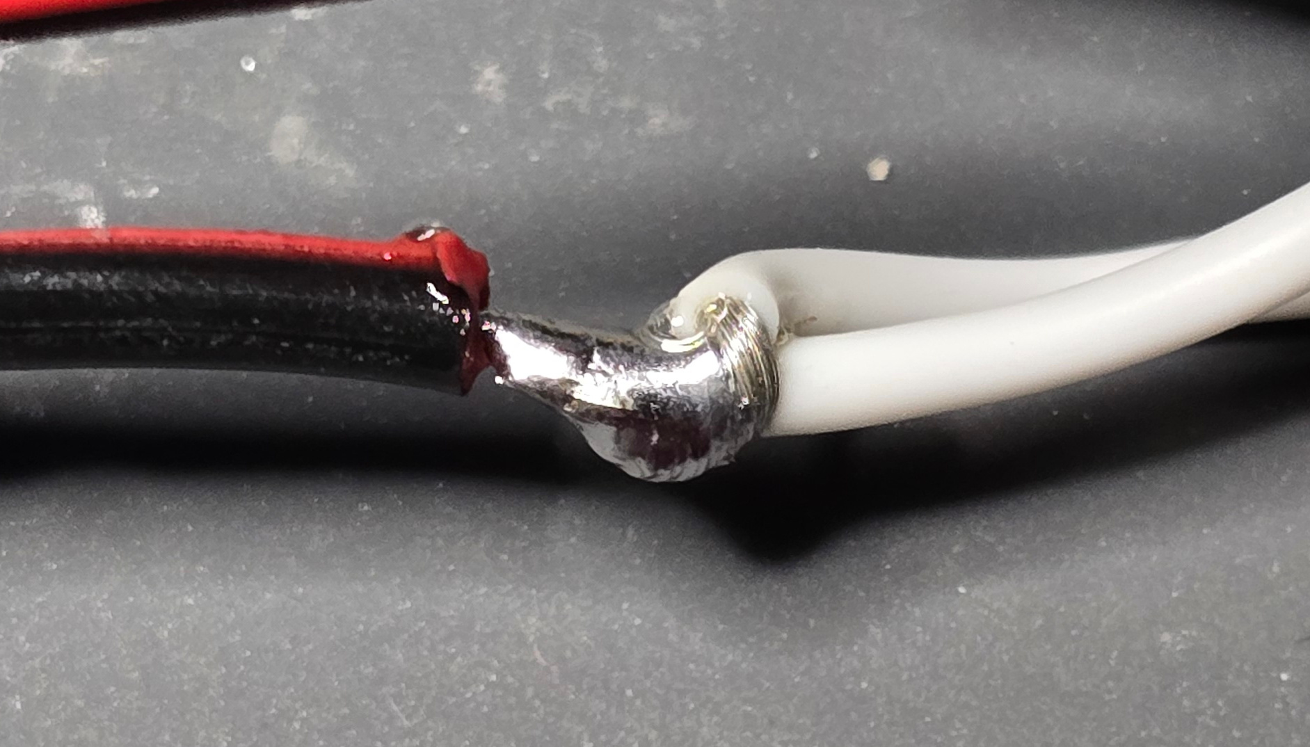
Fill the joint with solder and shrink the heat shrink around the joint.
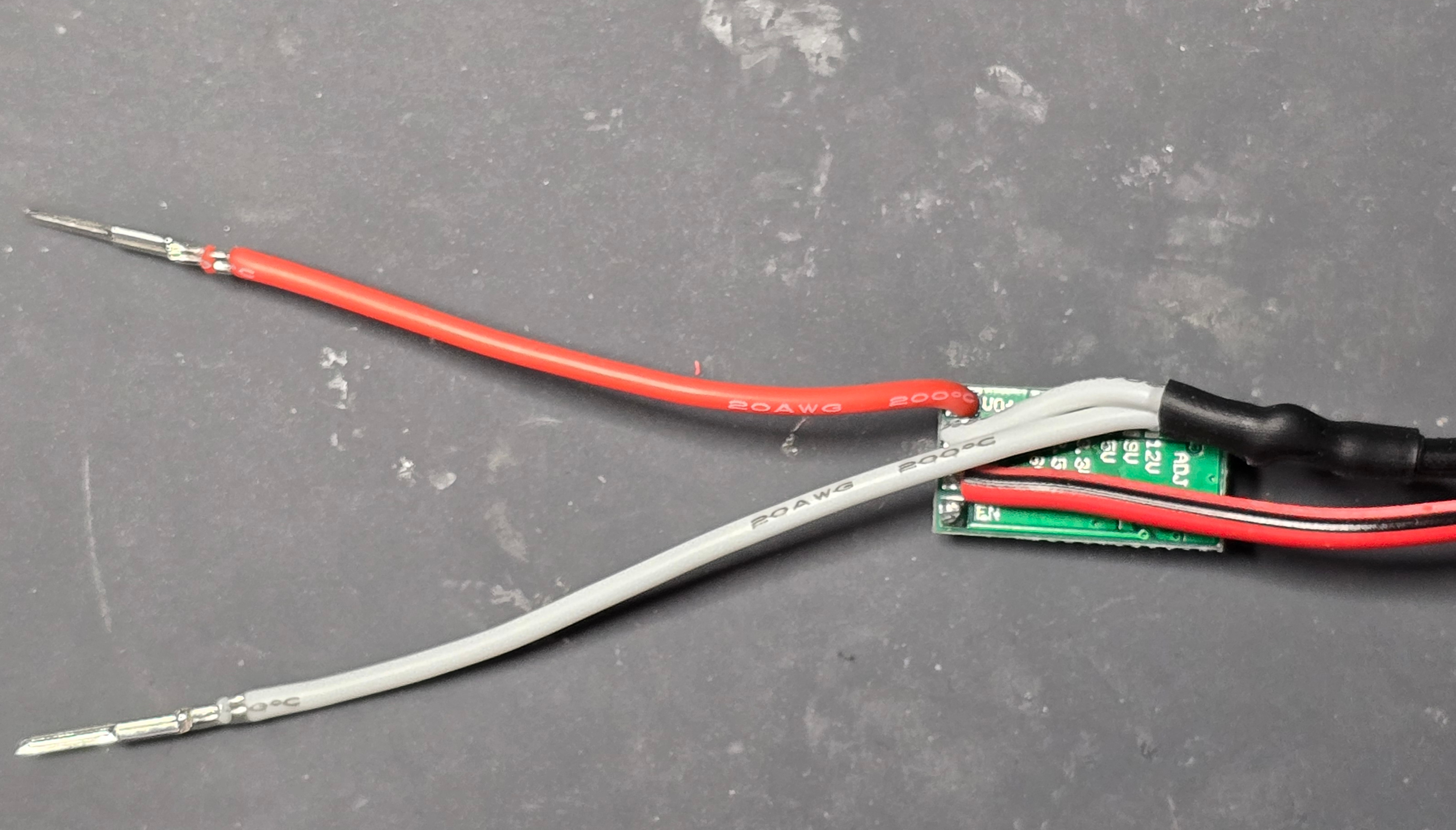
Trim the ends of the red and white wires to the same length. Crimp a male jst pin on each wire
TEST FOR 5v BEFORE THE NEXT STEP!
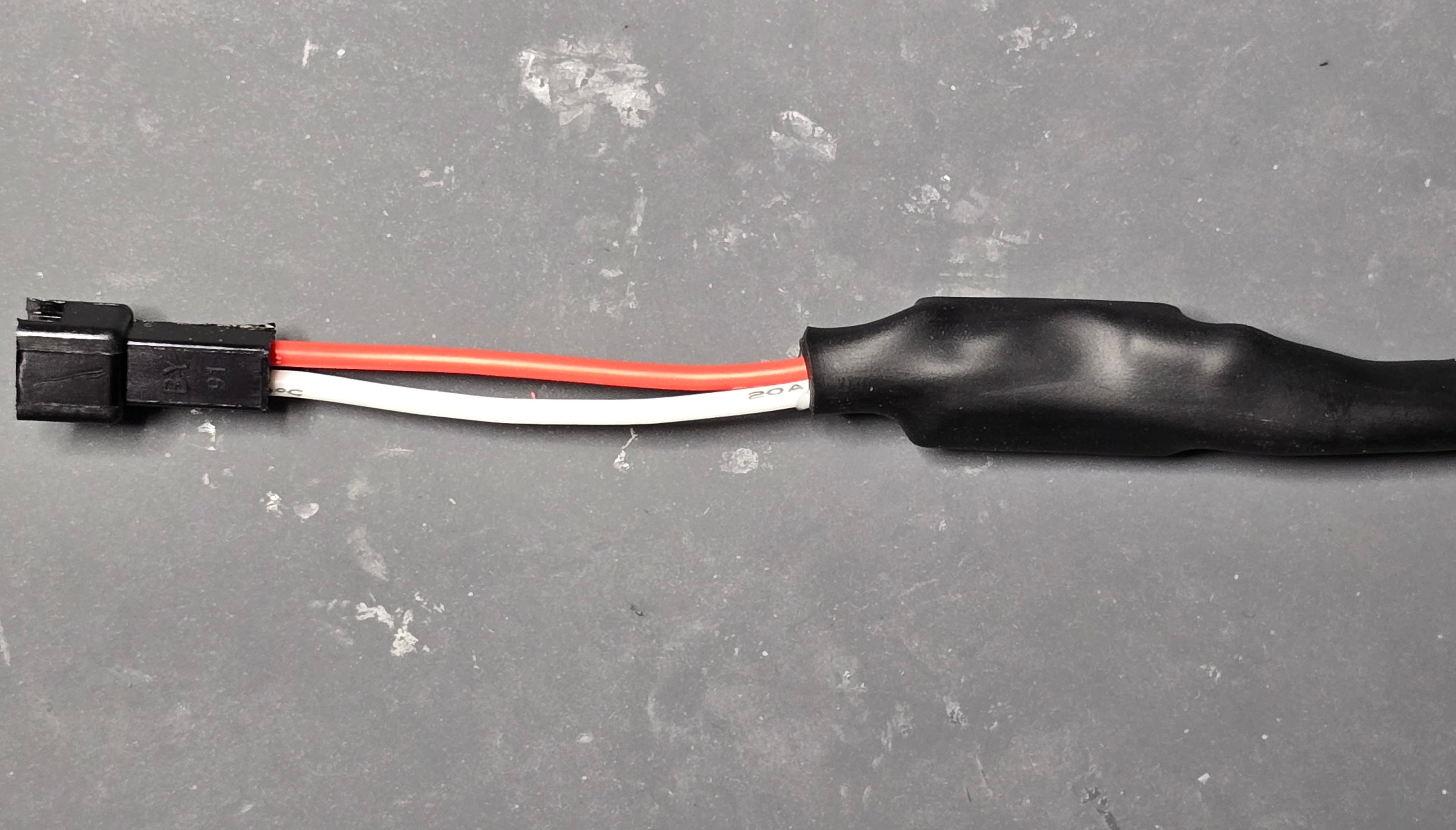
Feed the 3/8" heat shrink on and heat to shrink. Attach the jst connector housing.